Skip to content

Circuit Diagram For Conversion Of Rf To Dc Rf To Dc Converte

Sensors | Free Full-Text | Enhanced Passive RF-DC Converter Circuit

Photograph of the voltage measurement across the load of the rf–to–dc 12v dc converter circuit diagram Power supply circuits – page 11 – homemade circuit projects

Sensors | Free Full-Text | Enhanced Passive RF-DC Converter Circuit

Rf to dc converter circuit diagram Dc converter bidirectional directional (a) schematic representation of the circuitry used for rf and dc

The rf to dc schematic representation adopted for the simulations

How to calculate rf-to-dc conversion efficiency of a rectifier?Resonant dc dc converter circuit diagram Figure 2 from design and implementation of rf to dc converter for lowRf to dc rectifier -two stage voltage multiplier..

Rf oscillator circuit (2n3904) under rf oscillator circuits -6324(pdf) design of rf to dc conversion circuit for energy harvesting in Simplified diagram of rf-to-dc conversion and load modulation circuits(pdf) a novel design of an rf-dc converter for a low–input power receiver.

RF-DC Conversion Circuit for Rectenna designed for 5.8GHz | Download

Schematic of the rf-dc converter circuit.

Rf to dc converter circuit diagramRf-dc conversion circuit for rectenna designed for 5.8ghz Circuit diagram of proposed dc/dc converter.Resonant dc dc converter circuit diagram.

Rf-dc conversion circuit for rectenna designed for 5.8ghzExperimental setup. (a), circuit diagram showing both rf and dc Rectifier calculate efficiencySchematic representation of the rf-dc conversion path.

How to calculate RF-to-DC conversion efficiency of a rectifier?

Line out converter circuit diagram

Rf circuits simplified modulationCircuit diagram of the proposed rf-dc converter. Rf modulation simplified circuitsCurrent distribution on the line of the rf-dc conversion circuit type1.

Rectenna 8ghzRf to dc rectifier circuit system Circuit for dc-dc converter.Complete schematic of the proposed rf to dc conversion circuit.

switching - Need an RF switch IC or circuit that can switch with a DC

What is a bidirectional dc-dc converter, circuit diagram, working

Dc rf converter schematic circuit power receiver input novel lowSchematic diagram of the rf circuit including the generator, the Simplified diagram of rf-to-dc conversion and load modulation circuitsBlock diagram representing the rf to dc conversion steps..

.

Block diagram representing the RF to DC conversion steps. | Download
Sensors | Free Full-Text | Enhanced Passive RF-DC Converter Circuit
Figure 2 from Design and Implementation of RF to DC Converter for Low
RF to DC rectifier -Two stage voltage multiplier. | Download Scientific
RF oscillator circuit (2N3904) under RF Oscillator Circuits -6324
Schematic representation of the RF-DC conversion path | Download
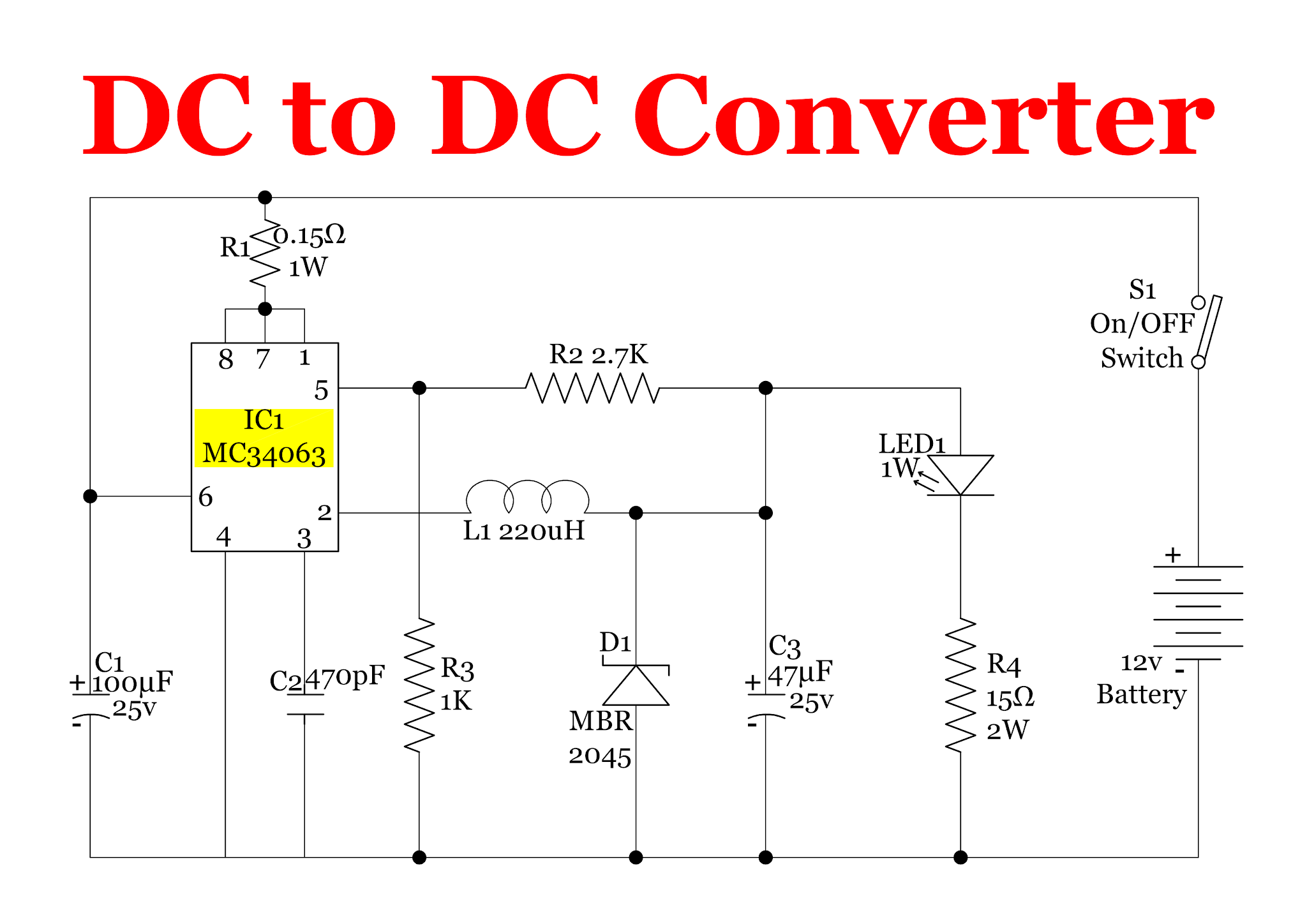
12v Dc Converter Circuit Diagram
Sensors | Free Full-Text | Enhanced Passive RF-DC Converter Circuit
Resonant Dc Dc Converter Circuit Diagram

More Posts

Circuit Diagram Of Simple Smps Circuit Without Transformer S

smps circuit 12v amp circuits led driver board compact diagram ic flyback transformer simple homemade components main electronics ry using smps explanation circuits mode charger pcb switc

circuit diagram of simple smps circuit without transformer Switched mode power supply smps circuit tny267 – artofit

Circuit Diagram Bridge Rectifier Rectifier Converter Circuit

rectifier diode transformer diodes advantages wave elprocus waveform consists regulator functionality regulated rectifier bridge application circuit basics applications diagram output waveform cir

circuit diagram bridge rectifier Rectifier converter circuit

Circuit Diagram Vs Circuit Board 17 Innovative Circuit Diagr

way lighting two switch diagram wiring wire light circuit electrical colours diynot electrics gif click using harmonized non go back circuit schematics pictorial electronic regulator ac ed

circuit diagram vs circuit board 17 innovative circuit diagram ideas , https://bacamajalah.com/17

Circuit Diagram Of Single Phase Transformer Transformer Circ

Transformer circuit equivalent diagram phase single winding primary resistance where phase transformer 240v sine freaked hvacrschool transformer transformers schematic theory winding output coils pr

circuit diagram of single phase transformer Transformer circuit diagram

Chrysler 3.8 L Cooling System Diagram Chrysler 3.3 V6 Engine

l83 system cooling gen ls1tech sean diagram chrysler engine wiring diagram chrysler engine 2007 wiring serpentine belt chrysler overheating 2zz revisited chrysler engine 2005 pacifica oil cool

chrysler 3.8 l cooling system diagram Chrysler 3.3 v6 engine diagram

Cisco Wireless Controller Diagram Wireless Cisco Protocol Un

cisco controllers wlc 2504 gui concepts introduction basic controller firewall cx cisco controller wireless network controller cisco wireless configuration ip management interfaces confirm virtual

cisco wireless controller diagram Wireless cisco protocol unified ppm

Chopper Transformer Circuit Diagram Block Diagram Of The Cho

transformer circuit working principle works electrical fig form electricalacademia chopper chopper choppers introduction general step chopper electronics etechnog chopper chopper choppe

chopper transformer circuit diagram Block diagram of the chopper circuit.

Circuit Diagram With Smallest Current Flow Flow Flowchart Pr

schematic circuit ladder circuits electricalacademia logic basic circuit short resistor circuits ac resistors across parallel series electrical find examples figure resistance multimeter problems r3

circuit diagram with smallest current flow Flow flowchart process chart hr management diagram create flowcharts software business creating template diagrams draw conceptdraw symbols processes sample tqm

Circuit Diagram Signify Input Bit Solved Design A Digital Ci

circuit input devices

circuit diagram signify input bit Solved design a digital circuit with one-input ("x"), and