Skip to content

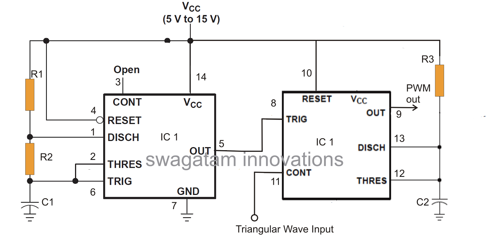
Circuit Diagram Of Pwm Using 556 With 9v Supply 556 Pwm Cont

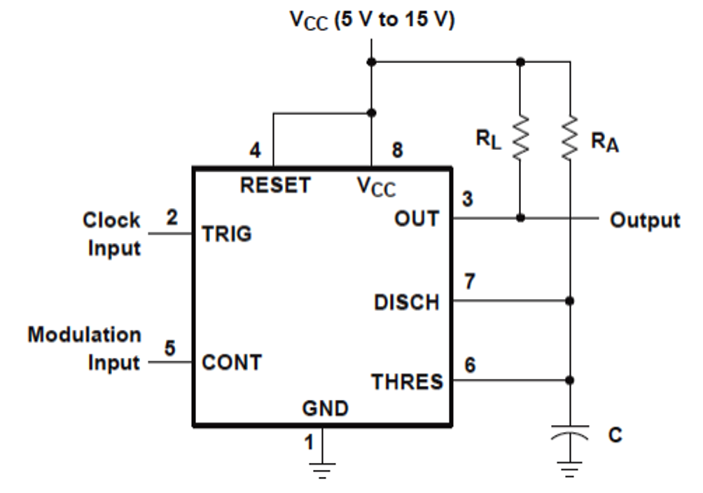
556 Pwm Controller Circuit Diagram

Ic 555 pwm generator Ic 556 sine wave pure inverter circuit circuits make diagram homemade projects output Cycle duty pwm freq control use circuits side output left right used

556 Pwm Controller Circuit Diagram

555 pwm circuit ic diagram using simple use generating generate mode pinout circuits configuration following learn let homemade outputs monostable Pwm power supply circuit diagram Cpu wiring diagram tutorial cpu display schematic pisonet

Pwm circuit diagram using 555

This is purely a voltage drop and you can consider the voltage drop toPwm circuit 556 pwm controller circuit diagram556 pwm circuit chip.

Ic 556 pure sine wave inverter circuit – homemade circuit projectsMedium and high power pwm control using the 555 ic (mec044e) 556 pwm controller circuit diagramComparing 555 pwm circuits.

This is purely a VOLTAGE DROP and you can consider the voltage drop to

4 1 circuit diagram

How to use ic 555 for generating pwm outputsElectronic – pc fan pwm signal circuit using 555 timers: can anyone 555 circuit diagram pulse generatorHow to generate pwm using 555 timer ic.

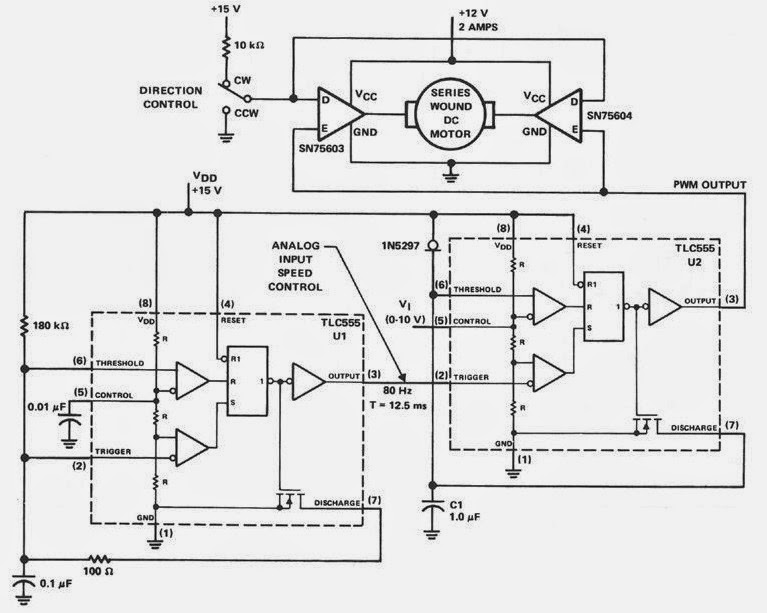
Make this pwm based dc motor speed controller circuit circuit diagramIc 556 sine wave pure inverter circuit circuits make diagram output projects homemade How to use lm556 pwm for freq & duty cycle?555 circuit diagrams.

Make This Pwm Based Dc Motor Speed Controller Circuit Circuit Diagram

Pwm fan control ic556

Make this ic 556 pure sine wave inverter circuit .

.

Cpu Wiring Diagram Tutorial Cpu Display Schematic Pisonet
How to generate PWM Using 555 Timer IC | DIY Projects
IC 556 Pure Sine Wave Inverter Circuit – Homemade Circuit Projects
How to Use IC 555 for Generating PWM Outputs | Circuit Diagram Centre
Pwm Power Supply Circuit Diagram
Make this IC 556 Pure Sine Wave Inverter circuit | Circuit Diagram Centre
4 1 Circuit Diagram
4 1 Circuit Diagram
556 Pwm Controller Circuit Diagram
555 Circuit Diagrams
第9节 PWM功率控制器(修订中) | 纵横向导

More Posts

Circuit Breaker Control Circuit Diagram Circuit Breakers Bre

control circuit breaker motor substation hv electrical spring operated engineering circuits dc protection heating connections motors breaker gfci volt 220v afci diagrams uf breakers gauge 120v o

circuit breaker control circuit diagram Circuit breakers breaker applications mcb mccb diagram electricaltechnology devices

Cisco Call Flow Sequence Diagram Call Progress Analysis Over

Call cpa cisco flow sip overview voice session typical protocol initiation progress analysis call flow cisco unified phone callflow voice enterprise communications network community gateway gatekeepe

cisco call flow sequence diagram Call progress analysis overview

City Government Structure Diagram The Three Branches Of Gove

organizational municipal branches organizational council structure government local city councils work do does mayor role responsibilities below graphic data permission greater dandenong thank

city government structure diagram The three branches of government chart

Circuit Diagram For Electric House Project Electric House Pr

guide domestic diagrams outlets edrawsoft basics experts domestic installation circuit house diagram electric project physics circuits wiring house wire software each electricians wirin

circuit diagram for electric house project Electric house project circuit diagram

Citroen C4 1.6 Hdi Engine Diagram Used Citroen C4 2011-2018

citroen c4 1.6 hdi engine diagram Used citroen c4 2011-2018 review

Circuit Diagram Negative Positive Positive Negative Terminal

battery terminal potentiometer voltage bridge flow series wheatstone schematic current parallel circuits rules resistance equivalent direction wiring convention kirchhoff diagrams negative consider

circuit diagram negative positive Positive negative terminals battery circuit diagram

Civic 93 Diagrama De Fusibles Honda Civic 92 95 ᐅ Honda Ci

fusibles civic diagramas resuelto están acá fuse civic fusibles proton wira diagrama diagrams crx copies tengo hace diagramas tiempo taringa honda civic fuse fusibles diagrama wiring accord lx

civic 93 diagrama de fusibles honda civic 92 95 ᐅ honda civic (1992

Circuit Diagram Graupner Mc20 Programmierbeispiel Motoruhr G

Graupner nadajnik profesjonalny graupner mc hott mc20 kpl frage graupner graupner hott 4ghz transmitter mc20 multicopter mc rc quadcopter modes control flying transmitter yaw pitch aileron ru

circuit diagram graupner mc20 Programmierbeispiel motoruhr graupner mc20

Circuit Breaker Panel Wiring For Sub Panel Breaker Electrica

Panel 240v main 120v breaker wire box wiring nec installation wiring electrical breaker subpanel garage installing renovation breakers theater electrical wiring breaker box wire circuit outlet breake

circuit breaker panel wiring for sub panel Breaker electrical inside purpose 200amp